Introduction
Marine engines, classified as heavy-duty machinery, require meticulous care during the prototype development phases. The engines work at extremely high speeds helical gear, resulting in significant strains and deflections in both the gears and other rotating components. In order to ensure the secure operation of the engine, it is imperative to reduce these stresses and deflections.

Table of Contents
Aim of the project : helical gear
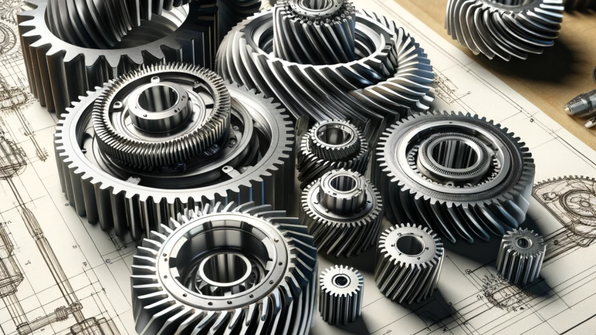
This project involved the creation of a helical gear using the CAD tool SolidWorks. The gear had a helical angle of 20 degrees, a face width of 32mm, and a pressure angle of 20. Using the CAE tool ANSYS Workbench, we applied high rotational speed, pressure, and torque values in the static structural analysis. This allowed us to determine the deformation of the gear, as well as the maximum stress values and safety factor.
objectives of the work
The objective of this project is to decrease the stress levels on the object by implementing three approaches to minimize stress.
- Implement a consistent and ongoing process of material modification.
- Develop a method to modify the value of a material constant.
Both the design and substance are undergoing changes.
Steel is currently the primary material utilized for helical gears. In this project, we are altering the design by adjusting the helix angle to 45 and 15 degrees, respectively. Additionally, we are evaluating these models using two different materials. The objective is to determine the most suitable material for this object based on the obtained results and graph values.
software tools used
CAD software:
based on your requirement we can use required tool
Computer-Aided Engineering (CAE) Tool:
based on your requirement we can use required tool
[…] Helical Gears are essential components in the field of mechanical engineering and design, as they are responsible for transmitting power and motion. Helical gears are notable among the several types of gears because of their distinctive design and practical characteristics. This blog post thoroughly examines helical gears, investigating their capabilities, benefits, drawbacks, uses, constraints, and prospects for future implementation in the industry. […]
[…] doors to various sectors. Graduates can find opportunities in automotive engineering, aerospace, manufacturing, robotics, and energy sectors, among others. This diversity in employment opportunities is one of […]
[…] engineering is a distinct field under aerospace engineering that specifically deals with the creation, advancement, and upkeep of aircraft operating […]