
The chassis frame is the backbone of a truck. Every other component, including the engine, gearbox, axles, cabin and body, is mounted on it, and it must carry the full payload while resisting bending, twisting and road shocks. In heavy-duty trucks, the frame is usually made of two long side members (longerons) joined by cross members (stiffeners), in a ladder frame layout. The shape of the side member cross-section has a big effect on the strength, stiffness and weight of the frame. This project compares C-section, I-section and box-section chassis frames with three materials to find the most efficient design.

Why Cross-Section Shape Matters
A beam’s resistance to bending depends mainly on how far its material sits from the centre, measured by the moment of inertia. A C-section is easy to make and widely used in trucks. An I-section puts more material in the top and bottom flanges, which gives high bending stiffness for its weight. A box section is closed, so it is very good at resisting twisting, but it uses more material and is heavier. Choosing between them is a classic trade-off between strength, stiffness, weight and cost.
About the Project
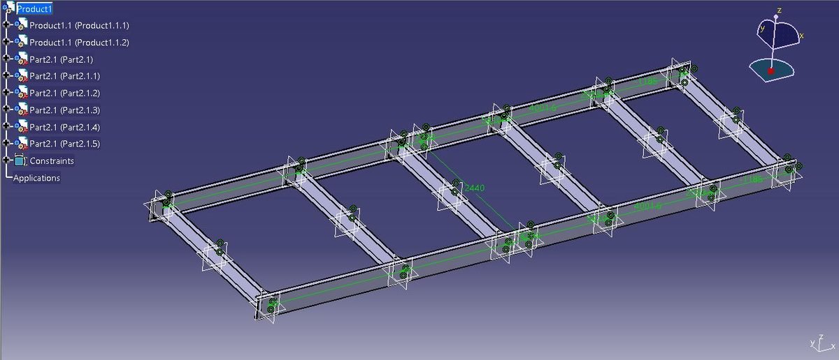
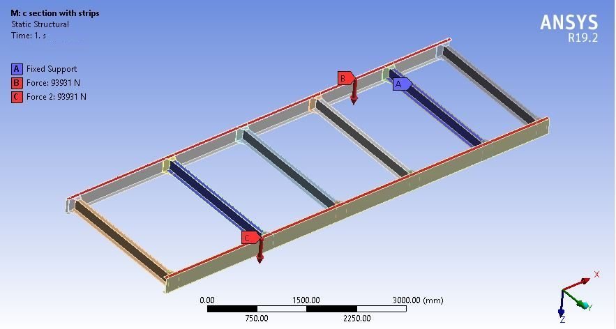
The side members, stiffeners and supports are modelled in CATIA for each cross-section and assembled into three complete ladder frames. The frames are imported into ANSYS Workbench, meshed, fixed at the supports, and loaded with a force of 93931 N to represent the heavy payload. Three materials are compared:
- Steel 710 (existing material)
- Steel 4130: a chromium-molybdenum alloy steel
- Al-7075: a high-strength aluminium alloy
For each section and material, the static structural analysis gives total deformation, stress, strain, maximum shear stress, safety factor and frame weight. A modal analysis then gives the first six natural frequencies of each frame.

Software Used
- CATIA: chassis frame modelling for all three cross-sections
- ANSYS Static Structural: deformation, stress, shear stress, safety factor and weight
- ANSYS Modal: natural frequencies
Analysis Results

Key Results (Preview)
Steel 710 frames under 93931 N:
| Section | Deformation (mm) | Stress (MPa) | Safety factor | Weight (kg) |
|---|---|---|---|---|
| C-section | 3.3906 | 183.76 | 2.2583 | 677.85 |
| I-section | 2.9897 | 79.891 | 5.1946 | 777.56 |
| Box section | 2.232 | 154.47 | 2.6867 | 1079.9 |
The three sections behave very differently in strength and weight, and switching to Al-7075 cuts the frame weight to about one-third. The full results for all materials, the natural frequencies and the recommended section for different priorities are given in the project report.
Why This Project Matters
Truck makers constantly work to reduce chassis weight so that vehicles can carry more payload and use less fuel, without losing strength. This project shows how cross-section shape and material choice together decide the performance of a frame, using a clear side-by-side comparison. It is a practical, industry-relevant project for automobile and mechanical engineering students.
Related Projects
Explore more design and analysis projects on similar topics:
- Manual Forklift Chassis Design and Analysis: Mild Steel, Steel 440C and Steel 304
- Design and Analysis of a Kia Carnival Wheel Rim with Al-6082 and Al-Li Alloy Under Multiple Passenger Loads (SolidWorks and ANSYS)
- Design and Analysis of a Military Jeep Leaf Spring Using Steel, FRP and MFRP Composite Materials (SolidWorks and ANSYS)
- Design and Analysis of a Two-Wheeler Shock Absorber Spring with Different Pitch and Coil Diameters: Steel vs Steel 416 (SolidWorks and ANSYS)
What You Get
- Design files: CATIA parts and assemblies of the C, I and box section chassis frames (with STEP files)
- Analysis files: ANSYS Workbench static structural and modal analysis files for all three sections and three materials
- Project document: complete report with methodology, results and conclusion
- Class explanation: a session that explains what was done in the project, step by step, so you can understand and present it confidently
Who Is This Project For?
This project suits B.Tech and B.E. final year students, diploma students looking for a strong design and analysis project, and M.Tech students who need a base model they can extend for their thesis. It is also useful for anyone who wants to learn chassis frame design, cross-section optimization and static and modal analysis in ANSYS on a real engineering problem instead of a textbook example.
Frequently Asked Questions
What is a ladder frame chassis?
A ladder frame has two long side members connected by several cross members, so it looks like a ladder from above. It is simple, strong and easy to repair, which is why it is used in trucks, buses and many SUVs.
Which chassis cross-sections are compared?
Three cross-sections are compared: C-section, I-section and box section. Each is modelled as a complete ladder frame and analysed under the same load so their strength, stiffness and weight can be compared.
What load is applied on the chassis?
The frame is fixed at its supports and a force of 93931 N is applied to represent the heavy payload. The same load is used for all three sections and all three materials.
Why is Al-7075 considered for a truck chassis?
Al-7075 is a high-strength aluminium alloy that is roughly one-third the weight of steel. Using it can greatly reduce frame weight, allowing more payload and better fuel economy, although its stiffness is lower than steel.
Get the Truck Chassis Optimization Project
Want this project for your final year, mini project or M.Tech work? Message us with your university, branch and deadline, and we will share the exact scope, files and report format.
Enquire about this project on WhatsApp or use the enquiry form on our home page. Browse more mechanical projects or 60+ mechanical engineering project ideas.
Interested in this project? Get the details, files and guidance from our team.
Enquire on WhatsApp