
As cities grow, the number of cars on Indian roads keeps rising, but parking space does not. Squeezing a car into a tight spot often needs many back-and-forth movements, wasting time and causing scrapes. A 360 degree wheel rotation vehicle solves this by letting all the wheels turn far enough that the vehicle can rotate on the spot or move sideways into a parking space. This project designs such a vehicle, explains its steering mechanism, and checks the strength of its main parts using finite element analysis.

How 360 Degree Wheel Rotation Works
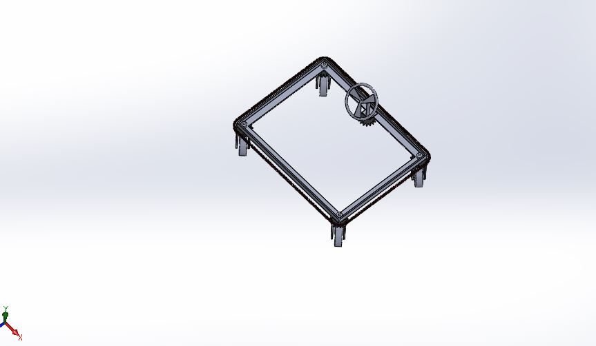
A normal car uses Ackermann steering, in which only the front wheels turn and the vehicle needs a large turning circle. In a 360 degree wheel rotation system, every wheel is mounted on a U-clamp that can swivel. The steering input is connected to all the wheels through a chain and sprocket arrangement, so turning the steering rotates every wheel together. With the wheels turned to suitable angles, the vehicle can turn about its own centre, which means it needs only as much space as its own length to change direction. The same idea is useful for load-carrying trolleys in factories, hospitals and railway platforms.
About the Project
Each part of the vehicle, including the chassis (frame), chain links, sprockets, U-clamps and tyres, is designed in SolidWorks and assembled into the complete vehicle. Design calculations are carried out for a load of 25 kg (245.25 N), giving a driving torque of 32591.58 N-mm at 60 rpm.
The three most important load-carrying parts are then analysed in ANSYS Workbench with real-time boundary conditions to find their maximum load capacity, and a new material is suggested for each:
- Chassis: mild steel (existing) and Steel 416
- Sprocket: steel (existing) and Steel 440C
- U-clamp: steel (existing) and EN-9
For each part and material, the deformation, stress, strain and safety factor are calculated and compared.
Software Used
- SolidWorks: part modelling and vehicle assembly
- ANSYS Static Structural: deformation, stress, strain and safety factor
Analysis Results


Key Results (Preview)
- The mild steel chassis frame can carry a maximum load of up to 550 N.
- Replacing mild steel with Steel 416 increases the strength of the frame by nearly 15%.
- The sprocket and U-clamp also perform better with their new materials.
The full stress, strain and safety factor results for each component are given in the project report.
Why This Project Matters
Parking is one of the biggest everyday problems in Indian cities, and zero-turn and crab-steering vehicles are now being developed by several car makers. This project combines mechanism design, chain drive calculations and structural analysis, and it can also be built as a working model, which makes it very popular for final year presentations. You can also see our 360 degree steering mechanism and Bluetooth-controlled 360 degree steering projects.
Related Projects
Explore more design and analysis projects on similar topics:
- Train Wheel Design and Transient Analysis: Steel, Steel 440C, Steel 416 and SAE 1020 (SolidWorks and ANSYS)
- Car Bumper Design and Impact Analysis – Polyetherimide, SiO₂ and Al₂O₃
- Go-Kart Chassis Design and Analysis: Steel, Al-6061 and Kevlar
- Six-Leg Robot with C-Shaped Legs – Design in Creo and Body Structural Analysis
What You Get
- Design files: SolidWorks parts and full assembly of the 360 degree wheel rotation vehicle (chassis, chain links, sprockets, U-clamps and tyres)
- Analysis files: ANSYS Workbench static structural files for the chassis, sprocket and U-clamp with existing and new materials
- Project document: complete report with methodology, results and conclusion
- Class explanation: a session that explains what was done in the project, step by step, so you can understand and present it confidently
Who Is This Project For?
This project suits B.Tech and B.E. final year students, diploma students looking for a strong design and analysis project, and M.Tech students who need a base model they can extend for their thesis. It is also useful for anyone who wants to learn mechanism design, chain and sprocket drives and component stress analysis in ANSYS on a real engineering problem instead of a textbook example.
Frequently Asked Questions
How does a 360 degree wheel rotation vehicle solve parking problems?
All the wheels can swivel through large angles, so the vehicle can rotate on the spot or move sideways. It needs only as much space as its own length to change direction, making it much easier to park in tight spaces.
How is the steering connected to the wheels?
Each wheel is mounted on a swivelling U-clamp, and the steering input is connected to all the wheels through a chain and sprocket arrangement, so turning the steering rotates every wheel together.
Which components are analysed in ANSYS?
The three main load-carrying parts are analysed: the chassis (frame), the sprocket and the U-clamp. Each is checked with its existing material and with a new suggested material.
Which new materials are suggested?
Steel 416 is suggested for the chassis instead of mild steel, Steel 440C for the sprocket, and EN-9 for the U-clamp, each chosen to improve the strength of the component.
Get the 360 Degree Wheel Rotation Vehicle Project
Want this project for your final year, mini project or M.Tech work? Message us with your university, branch and deadline, and we will share the exact scope, files and report format.
Enquire about this project on WhatsApp or use the enquiry form on our home page. Browse more mechanical projects or 60+ mechanical engineering project ideas.
Interested in this project? Get the details, files and guidance from our team.
Enquire on WhatsApp