
Milling is a machining process that removes material using a rotating cutter with many cutting edges. Because several edges cut at once, milling achieves high material removal rates with a good surface finish. Common operations include facing, slotting, drilling, T-slot cutting and thread milling, where a cutter with a thread profile is moved around and along a hole to cut an internal or external thread. The shape of the thread profile and the material of the cutter decide how much load the tool can take and how fast it can be fed into the work.

Cutter Designs
Three thread milling cutters are designed in SolidWorks, each with a different thread profile:
- Rectangular (square) thread milling cutter.
- Triangular (V) thread milling cutter.
- Rhombic thread milling cutter.
A mild steel workpiece plate with a pre-cut cavity is also modelled so that the cutter can be analysed in contact with the work.
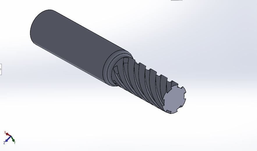

About the Project
Each cutter and workpiece assembly is analysed in ANSYS Workbench using transient structural analysis. The loads represent real milling conditions:
- A downward force of 2500 N, representing a spindle weight of about 250 kg.
- A spindle rotational speed of about 850 rpm.
- An axial feed velocity, which is increased step by step to find the feed each cutter can take.
Four tool materials are compared: SAE 1020, high speed steel (HSS), SCM 415 and tungsten carbide.


Software Used
- SolidWorks: cutter and workpiece modelling
- ANSYS Workbench: transient structural analysis
Analysis Setup


The deformation, stress and safety factor results, the required axial velocity for each cutter, and the final choice of cutter profile and material are explained in the project report.
Cutting Tool Materials
- SAE 1020: a low carbon steel, used here as a baseline.
- High speed steel: tough tool steel alloyed with tungsten, molybdenum, chromium and vanadium, widely used for cutters and drills.
- SCM 415: a chromium-molybdenum alloy steel.
- Tungsten carbide: an extremely hard material that keeps its edge at high cutting speeds.
Why Thread Profile Matters
The thread profile changes how the cutting load is shared along the cutter. A square profile has flat flanks that cut with a wide edge, so it pushes back with a large force. A V-shaped triangular profile enters the material gradually and spreads the load over sloping flanks. A rhombic profile sits between the two. These differences change the stress at the cutting edges, how much the tool deflects and how fast the cutter can be fed into the workpiece before it is overloaded. Comparing all three profiles with four tool materials shows which combination lets the tool cut efficiently while staying within its strength limits.
Real-World Applications
- Thread milling on CNC machining centres.
- Aerospace and automotive: threads in hard alloys.
- Tool design: choosing profile and material for cutters.
- Die and mould making.
Key Concepts Covered
- Milling process and cutting parameters.
- Thread profiles: square, V and rhombic.
- Transient structural analysis with rotation and feed.
- Tool materials: HSS and carbide.
Project Workflow
- Study milling operations and thread milling.
- Model three thread milling cutters and workpieces in SolidWorks.
- Apply spindle force, rotation and axial feed in ANSYS.
- Run transient analysis for four tool materials.
- Compare required feed and results in the report.
Why This Project Matters
Cutting tools decide the speed and quality of manufacturing. This project links machining theory with FEA, a strong topic for mechanical and production engineering students.
Related Projects
Explore more design and analysis projects on similar topics:
- Hydraulic Scissor Lift Design and Analysis for an 80 kN Load
- Pneumatic Sheet Metal Bending and Cutting Machine: Design and Analysis for Aluminium and Galvanized Iron Sheets (SolidWorks and ANSYS)
- Portable Grain Packing Machine Design and Analysis: Steel vs Grey Cast Iron vs Aluminium Alloy (SolidWorks and ANSYS)
- Belt Conveyor Design and Analysis: Rubber, CFRP and Basalt Fibre Belts with Steel, SS-304 and Al-7075 Rollers (ANSYS)
What You Get
- Design files: SolidWorks models of rectangular, triangular and rhombic thread milling cutters and workpiece plates
- Analysis files: ANSYS Workbench transient structural files for three cutters and four materials
- Project document: complete report with methodology, results and conclusion
- Class explanation: a session that explains what was done in the project, step by step, so you can understand and present it confidently
Who Is This Project For?
This project suits B.Tech and B.E. final year students, diploma students looking for a strong design and analysis project, and M.Tech students who need a base model they can extend for their thesis. It is also useful for anyone who wants to learn SolidWorks cutter modelling and ANSYS transient structural analysis on a real engineering problem instead of a textbook example.
Frequently Asked Questions
Which cutter profiles are compared?
Rectangular, triangular and rhombic thread milling cutters.
What loads are applied?
A 2500 N spindle force, about 850 rpm rotation and an axial feed velocity in transient structural analysis.
Which tool materials are used?
SAE 1020, high speed steel, SCM 415 and tungsten carbide.
Which software is used?
SolidWorks for modelling and ANSYS Workbench for transient structural analysis.
Get the Thread Milling Cutter Project
Want this project for your final year, mini project or M.Tech work? Message us with your university, branch and deadline, and we will share the exact scope, files and report format.
Enquire about this project on WhatsApp or use the enquiry form on our home page. Browse more mechanical projects or 60+ mechanical engineering project ideas.
Interested in this project? Get the details, files and guidance from our team.
Enquire on WhatsApp