
The camshaft is the component that controls an engine’s breathing. Each lobe on the shaft pushes open an intake or exhaust valve at exactly the right moment in the cycle, and the shaft must keep doing this millions of times while spinning at high speed and carrying contact loads from the valve train. In a V6 engine, with six cylinders in two banks, the camshaft is long and carries many lobes, so stiffness, strength and vibration behaviour all matter. A failed camshaft means poor valve timing, loss of power or a complete engine stop. This project designs a V6 engine camshaft and studies how four different materials behave under the same working loads.

How a Camshaft Works
The camshaft is driven by the crankshaft through a belt, chain or gears, and turns at half the crankshaft speed in a four-stroke engine. As each egg-shaped lobe rotates, it lifts a follower or rocker that opens a valve, and a spring closes the valve again. The lobes therefore see repeated contact pressure, while the shaft as a whole sees bending, torsion and rotational loads. Traditionally camshafts are made from forged steel or cast iron, but lighter or stronger alternatives are always being explored to reduce weight and improve performance.
About the Project
The camshaft is modelled in SolidWorks and imported into ANSYS Workbench. After meshing, the model is analysed with fixed supports at the bearing locations, a pressure of 22.5 MPa on the lobes and a rotational velocity of 2250 RPM. Two analyses are carried out:
- Static structural analysis to find total deformation, equivalent stress, equivalent strain and factor of safety.
- Modal analysis to find the natural frequencies of the camshaft, so that resonance at running speed can be avoided.
Four materials are compared: forged steel (the existing material), aluminium alloy Al-3003, EN-9 steel and aluminium alloy Al-7475.

Software Used
- SolidWorks: 3D camshaft modelling
- ANSYS Workbench: meshing, static structural and modal analysis
Analysis Results

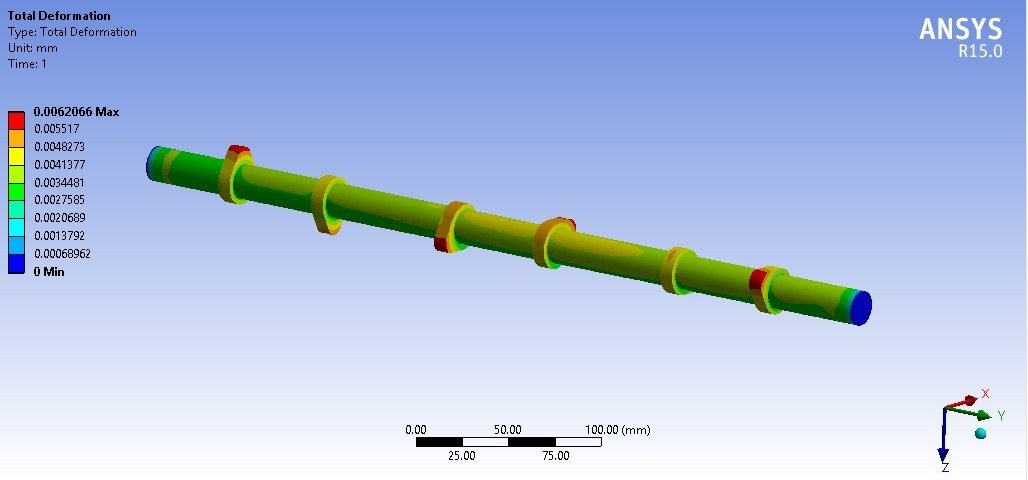

Key Results (Preview)
| Material | Deformation (mm) | Equivalent stress (MPa) | Factor of safety | Mode 1 frequency (Hz) |
|---|---|---|---|---|
| Forged steel | 0.0062066 | 168.3 | 1.4855 | 384.95 |
| Al-3003 | 0.017356 | 146.86 | 1.8385 | 392.44 |
| EN-9 | 0.0050677 | 146.81 | 2.3841 | 351.23 |
| Al-7475 | 0.10818 | 137.79 | 3.2659 | 377.46 |
All four materials stay within safe limits, but they differ clearly in stiffness and safety margin. The detailed comparison, including the strain results and higher modes, and the final material recommendation are explained in the project report.
Project Workflow
- Study the camshaft geometry and the loads it carries in a V6 engine.
- Build the 3D camshaft model with all lobes and bearing journals in SolidWorks.
- Import the model into ANSYS, assign each material and generate a fine mesh.
- Apply fixed supports, the 22.5 MPa lobe pressure and the 2250 RPM rotational velocity.
- Solve the static structural analysis and record deformation, stress, strain and safety factor.
- Run the modal analysis to find the natural frequencies and mode shapes.
- Compare all four materials and draw conclusions in the report.
Why This Project Matters
Camshafts are a classic automobile engineering topic that combines machine design, materials and finite element analysis. This project shows students how to model a real engine part, apply realistic loads, and judge materials using both static and dynamic results. It is a strong choice for mechanical and automobile engineering final-year projects.
Related Projects
Explore more design and analysis projects on similar topics:
- Two-Wheeler Piston and Connecting Rod: Static and Thermal Analysis with Design Optimisation
- Engine Rocker Arm Design and Analysis: Static and Modal with Steel and Carbon Steel
- Single Cylinder Crankshaft Design and Analysis: Cast Iron, EN9, SAE 1045 and SAE 1137
- Petrol Engine Flywheel Design and Analysis: Steel, 440C, CFRP and Al-7075
What You Get
- Design files: SolidWorks 3D model of the V6 engine camshaft
- Analysis files: ANSYS Workbench static structural and modal analysis files for all four materials
- Project document: complete report with methodology, results and conclusion
- Class explanation: a session that explains what was done in the project, step by step, so you can understand and present it confidently
Who Is This Project For?
This project suits B.Tech and B.E. final year students, diploma students looking for a strong design and analysis project, and M.Tech students who need a base model they can extend for their thesis. It is also useful for anyone who wants to learn camshaft design, structural and modal analysis, and material comparison in ANSYS on a real engineering problem instead of a textbook example.
Frequently Asked Questions
What does a camshaft do in an engine?
The camshaft opens and closes the intake and exhaust valves at the correct time. Its lobes push the valves open as it rotates, and springs close them again.
Which materials are compared for the camshaft?
Forged steel (the existing material), aluminium alloy Al-3003, EN-9 steel and aluminium alloy Al-7475 are compared under the same loads.
What loads are applied in the analysis?
The camshaft is fixed at its supports, with a pressure of 22.5 MPa on the lobes and a rotational velocity of 2250 RPM.
Why is modal analysis done on a camshaft?
Modal analysis finds the natural frequencies of the camshaft. Knowing them helps designers avoid resonance with the engine’s running speed, which could cause severe vibration or fatigue failure.
Get the V6 Engine Camshaft Project
Want this project for your final year, mini project or M.Tech work? Message us with your university, branch and deadline, and we will share the exact scope, files and report format.
Enquire about this project on WhatsApp or use the enquiry form on our home page. Browse more mechanical projects or 60+ mechanical engineering project ideas.
Interested in this project? Get the details, files and guidance from our team.
Enquire on WhatsApp