
A V6 engine has six cylinders arranged in two banks of three, set at an angle to each other – usually 60° or 90° – and driving a single crankshaft. This layout makes the engine much shorter than an inline-six and more compact than a V8, so it fits well in front-wheel-drive cars where the engine sits sideways. V6 engines usually range from about 2.0 to 4.3 litres and are popular in mid-size cars because they run more smoothly than a large four-cylinder engine and cost less to build than a V8.
This project builds a complete V6 engine model in SolidWorks, part by part, and sets up the piston for structural and thermal study with a ceramic top coating.
Components Modelled in SolidWorks
Every major moving part of the engine was modelled separately and then assembled with mates so that the mechanism can rotate:
- Piston with piston pin, piston rings and plug
- Connecting rod – top and bottom halves joined with bolts and nuts
- Crankshaft with six crank throws
- Camshaft, cam base and cam rods (push rods)
- Inlet and exhaust valves
- Cylinder block with two banks of three cylinders


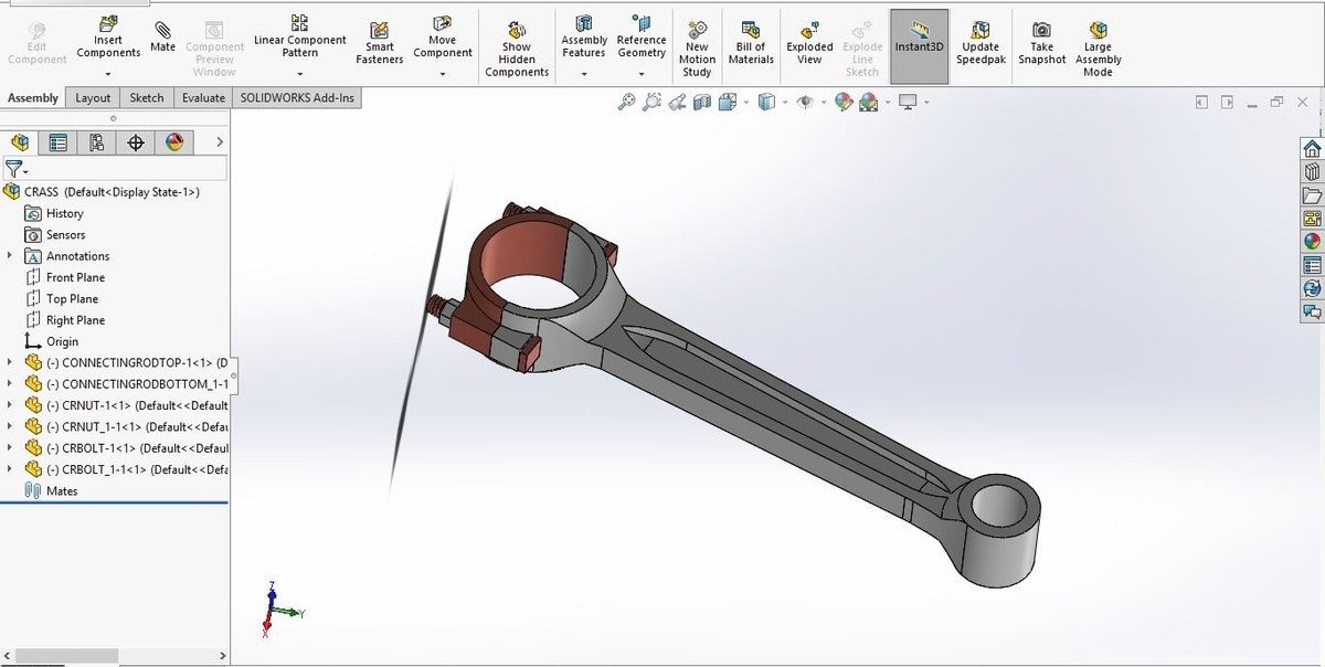
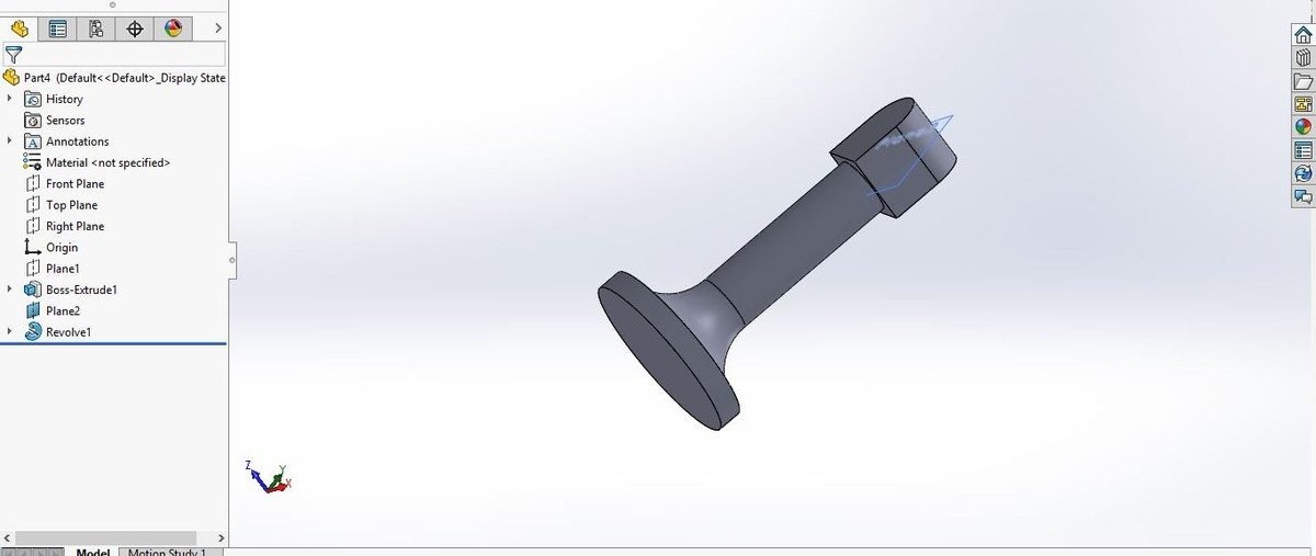

Complete Engine Assembly
The sub-assemblies – the piston-and-rod sets, valves and camshaft parts – were brought together on the crankshaft inside the V-shaped block. The exploded view shows how each part fits into the engine, and the assembly can be animated to show the pistons moving in sequence as the crankshaft turns.
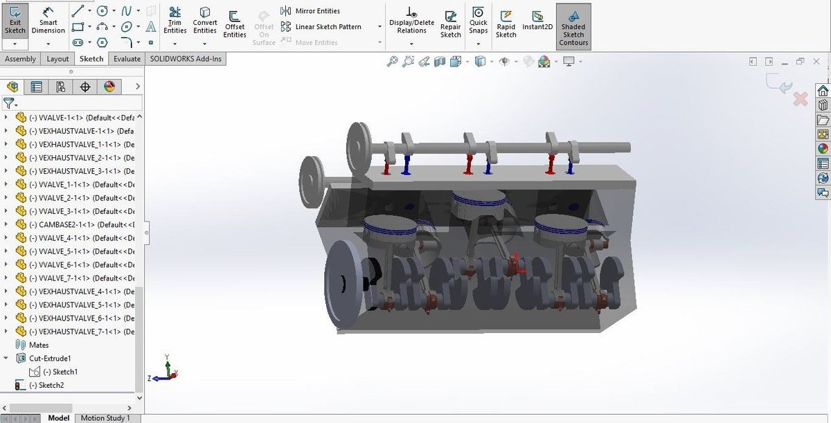

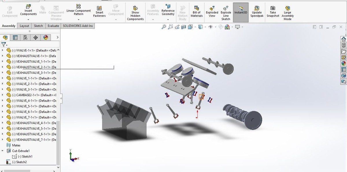
Ceramic-Coated Piston Concept
The piston crown faces the hottest gases in the engine. To raise efficiency, the project proposes adding a 0.4 mm ceramic coating on the piston top. Ceramics are inorganic, non-metallic materials that can work at temperatures of roughly 1,000 °C to 1,600 °C. A thin ceramic layer acts as a thermal barrier: less heat leaks into the piston and cooling system, so more of the fuel energy can be turned into work, and the metal underneath runs cooler.
| Item | Selection |
|---|---|
| Base piston material | Cast iron |
| Ceramic coating 1 | Zirconium-based ceramic |
| Ceramic coating 2 | Silicon dioxide (SiO₂) |
| Coating thickness | 0.4 mm |
Planned Analysis in ANSYS
The SolidWorks parts are prepared for ANSYS Workbench to find the maximum load each main part – the piston and connecting rod – can carry, and to compare the plain cast-iron piston with the two ceramic-coated versions under structural and thermal loads. The full results, the comparison of coatings and their limitations are covered in the project report.
Why This Project Matters
Building a full multi-cylinder engine in CAD teaches assembly modelling, mates and motion – skills used every day in automotive design offices. Thermal barrier coatings are also a real research area for improving engine efficiency and reducing emissions, so combining both gives a strong final-year project.
Real-World Applications
- Automotive engine design and packaging
- Thermal barrier coatings for pistons and combustion chambers
- Engine animation and teaching models
- CAD assembly practice for mechanical students
Related Projects
Explore more design and analysis projects on similar topics:
- V6 Engine Camshaft Design and Analysis: Forged Steel vs Al-3003, EN-9 and Al-7475 (SolidWorks and ANSYS)
- Two-Wheeler Piston and Connecting Rod: Static and Thermal Analysis with Design Optimisation
- Engine Rocker Arm Design and Analysis: Static and Modal with Steel and Carbon Steel
- Single Cylinder Crankshaft Design and Analysis: Cast Iron, EN9, SAE 1045 and SAE 1137
What You Get
- Design files: SolidWorks parts and full assembly of a V6 engine
- Analysis files: Piston set-up for ANSYS with 0.4 mm ceramic coating (zirconium, SiO₂)
- Project document: complete report with methodology, results and conclusion
- Class explanation: a session that explains what was done in the project, step by step, so you can understand and present it confidently
Who Is This Project For?
This project suits B.Tech and B.E. final year students, diploma students looking for a strong design and analysis project, and M.Tech students who need a base model they can extend for their thesis. It is also useful for anyone who wants to learn How a V6 engine is built part by part and how ceramic coatings protect pistons on a real engineering problem instead of a textbook example.
Frequently Asked Questions
What parts of the V6 engine are modelled?
The piston, piston pin and rings, connecting rod, crankshaft, camshaft parts, valves and the V-shaped cylinder block, all assembled in SolidWorks.
What is the ceramic coating idea?
A 0.4 mm ceramic layer on the piston crown acts as a thermal barrier, keeping heat in the combustion chamber.
Which ceramics are considered?
A zirconium-based ceramic and silicon dioxide, applied on a cast-iron piston.
Are analysis results included?
The piston analysis and the coating comparison are explained in the project report.
Get the V6 Engine Project
Want this project for your final year, mini project or M.Tech work? Message us with your university, branch and deadline, and we will share the exact scope, files and report format.
Enquire about this project on WhatsApp or use the enquiry form on our home page. Browse more mechanical projects or 60+ mechanical engineering project ideas.
Interested in this project? Get the details, files and guidance from our team.
Enquire on WhatsApp