
Helical gears are used wherever power must be transmitted smoothly and quietly at high speed – in car and marine gearboxes, turbines and industrial drives. Unlike spur gears, their teeth are cut at an angle (the helix angle) to the axis. The teeth engage gradually, so more than one tooth carries load at a time, which reduces noise and shock. The helix angle, however, also changes the stress inside the teeth, so it is one of the most important choices in gear design.
Marine and heavy-duty engines run at very high speeds, which produce large stresses and deflections in their gears. This project designs a high-speed helical gear and uses the Finite Element Method to see how the helix angle and the material affect its strength.
Gear Design and Calculations
The gear dimensions – number of teeth, normal and transverse pitch, module, pitch diameter and centre distance – were calculated first for the pinion and gear pair. The gear was then modelled in Creo with a face width of 32 mm and a pressure angle of 20°.

Three versions of the gear were built, keeping all other dimensions the same:
- 20° helix angle – the existing design used as the reference
- 15° helix angle – a smaller angle
- 45° helix angle – a much larger angle

Materials
Steel is the material normally used for helical gears. Two high-strength aluminium alloys, Al-6061 and Al-7475, were also studied because they are much lighter than steel.
ANSYS Model and Boundary Conditions
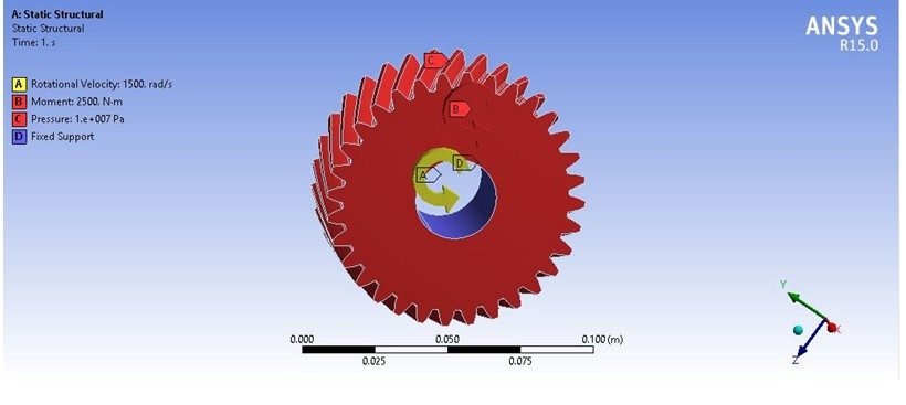
Each gear was imported into ANSYS Workbench and meshed with tetrahedral elements. The bore was fixed, and the gear was loaded with:
| Load | Value |
|---|---|
| Rotational velocity | 1500 rad/s |
| Moment (torque) | 2500 N·m |
| Pressure on teeth | 1×10⁷ Pa (10 MPa) |


Results – 20° Helix Angle (Existing)
| Result | Steel | Al-6061 | Al-7475 |
|---|---|---|---|
| Deformation (mm) | 0.020957 | 0.062102 | 0.060349 |
| Stress (MPa) | 158.51 | 159.08 | 159.06 |
| Factor of safety | 1.5772 | 1.7349 | 2.8292 |


Results – 15° Helix Angle
| Result | Steel | Al-6061 | Al-7475 |
|---|---|---|---|
| Deformation (mm) | 0.021176 | 0.062731 | 0.060961 |
| Stress (MPa) | 164.13 | 164.78 | 164.76 |
| Factor of safety | 1.5232 | 1.6749 | 2.7313 |
Results – 45° Helix Angle
| Result | Steel | Al-6061 | Al-7475 |
|---|---|---|---|
| Deformation (mm) | 0.022696 | 0.067922 | 0.065994 |
| Stress (MPa) | 133.28 | 131.34 | 131.31 |
| Factor of safety | 1.8757 | 2.1015 | 3.427 |


The stress changes clearly with the helix angle, while the deformation depends mainly on the stiffness of the material – the aluminium gears deflect about three times more than steel. The best combination of helix angle and material for a high-speed gear is explained in the project report.
Why Helix Angle Matters
A larger helix angle spreads the load over a longer contact line, because each tooth is in mesh for a longer time. This usually lowers the stress in the tooth and makes the gear quieter. The trade-off is a larger axial (thrust) force along the shaft, which the bearings must carry. A smaller helix angle reduces the thrust load but concentrates the stress on fewer teeth. Comparing several angles under the same loads shows the designer exactly how much stress is saved and what it costs in thrust and deflection.
Real-World Applications
- Marine and automobile gearboxes
- Turbine reduction gears and industrial drives
- Light-weight gear design for high-speed machinery
- Machine design and FEA projects on gears
Related Projects
Explore more design and analysis projects on similar topics:
- Three-Stage Planetary Gearbox Design and Analysis: Steel 4340 vs Al-7075
- Design and Analysis of a Spur Gear: Grey Cast Iron vs High-Speed Steel M2 (SolidWorks and ANSYS)
- Design and Analysis of an Electric Vehicle Differential: Mild Steel vs 8620 Steel, Al-356 and Al-7075 (SolidWorks and ANSYS)
- Static and Dynamic Analysis of a Gearbox Casing Cover: Cast Iron vs Al-7075 and CFRP (SolidWorks and ANSYS)
What You Get
- Design files: Gear calculations and Creo models with 15°, 20° and 45° helix angles
- Analysis files: ANSYS static structural at 1500 rad/s and 2500 N·m
- Project document: complete report with methodology, results and conclusion
- Class explanation: a session that explains what was done in the project, step by step, so you can understand and present it confidently
Who Is This Project For?
This project suits B.Tech and B.E. final year students, diploma students looking for a strong design and analysis project, and M.Tech students who need a base model they can extend for their thesis. It is also useful for anyone who wants to learn How helix angle and material change gear deformation, stress and safety factor on a real engineering problem instead of a textbook example.
Frequently Asked Questions
What is the helix angle of a helical gear?
It is the angle between the gear teeth and the gear axis. This project compares 15°, 20° (existing) and 45°.
What loads are applied in the analysis?
A rotational velocity of 1500 rad/s, a moment of 2500 N·m and a 10 MPa pressure on the teeth, with the bore fixed.
Which materials are compared?
Steel, Al-6061 and Al-7475 aluminium alloys.
Which design is best?
The best helix angle and material combination is explained in the project report.
Get the Helical Gear Project
Want this project for your final year, mini project or M.Tech work? Message us with your university, branch and deadline, and we will share the exact scope, files and report format.
Enquire about this project on WhatsApp or use the enquiry form on our home page. Browse more mechanical projects or 60+ mechanical engineering project ideas.
Interested in this project? Get the details, files and guidance from our team.
Enquire on WhatsApp