
An aircraft fuselage is not built as one piece. It is made of skin panels, frames and long stiffeners called stringers, and these parts have to be joined wherever one section ends and the next begins. The joint that connects two stringers or skin sections end to end is called a splice joint. A splice plate is placed over the two parts and fastened with rows of rivets, so that the load can flow from one member into the next without a weak point. Because fuselage joints carry cabin pressure and flight loads on every flight, their shape and material decide how much stress builds up around the rivet holes. This project compares four common stringer section shapes used for splice joints.
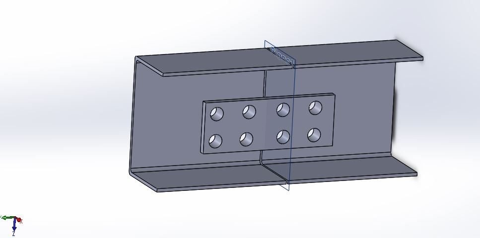
Stringer Section Shapes Studied
Four splice joint geometries are modelled, each named after the cross-section of the stringer:
- C joint: a channel section with two flanges and a web.
- L joint: an angle section with one vertical leg and one horizontal leg.
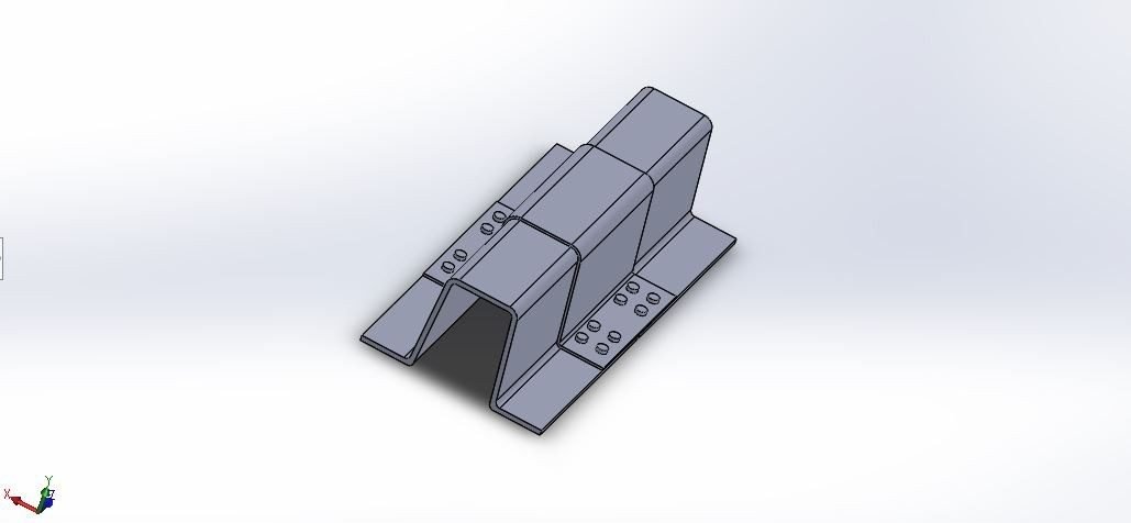
- Omega joint: a hat-shaped section that is closed against the skin, giving a box-like structure.
- Z joint: a section with flanges pointing in opposite directions, widely used in fuselage stringers.
In every case the two stringer pieces meet in the middle and a splice plate with a pattern of rivet holes joins them.
About the Project
All four joints are modelled in SolidWorks from 2D sketches that are extruded into sheet sections, with the splice plate and rivet holes added. The models are then imported into ANSYS Workbench for static structural analysis and modal analysis. In the static study, one end of the joint is held by a fixed support, a pressure of 5 MPa is applied on the joint face and a force of 50 N acts at the rivet locations. The outputs are total deformation, equivalent (von-Mises) stress and safety factor.
Two aerospace aluminium alloys are compared:
- Al-2024: the classic fuselage skin and stringer alloy, with good fatigue resistance (yield strength 325 MPa).
- Al-7075: a higher-strength alloy used for heavily loaded structure (yield strength 503 MPa).

Software Used
- SolidWorks: sketching and modelling of the four splice joints
- ANSYS Workbench: meshing, static structural and modal analysis
Analysis Setup

Analysis Results
The static results for each joint shape with both alloys are listed below.
| Joint | Material | Deformation (mm) | Equivalent stress (MPa) | Safety factor |
|---|---|---|---|---|
| C joint | Al-2024 | 0.88998 | 196.45 | 1.6544 |
| C joint | Al-7075 | 0.90735 | 196.4 | 2.5605 |
| L joint | Al-2024 | 0.28108 | 114.02 | 2.8504 |
| L joint | Al-7075 | 0.28657 | 114.0 | 4.4115 |
| Omega joint | Al-2024 | 0.061026 | 34.933 | 9.3035 |
| Omega joint | Al-7075 | 0.062217 | 34.93 | 14.399 |
| Z joint | Al-2024 | 0.31835 | 122.64 | 2.6499 |
| Z joint | Al-7075 | 0.32457 | 122.6 | 4.1013 |


The table shows that the joint shape changes the stress far more than the material does. For the same load, the stress in a given shape is almost identical for both alloys, while the safety factor rises with the higher yield strength of Al-7075. The closed omega section deforms the least, and the open C section deforms the most. The modal results, the full comparison and the final recommendation are explained in the project report.
Real-World Applications
- Fuselage assembly: joining stringers and skin panels between fuselage barrel sections.
- Wing structure: splicing wing stringers and spar caps.
- Repair design: doubler and splice repairs on damaged aircraft structure.
- Light aircraft and UAVs: choosing section shapes for lightweight frames.
Key Concepts Covered
- Semi-monocoque structure: how skin, frames and stringers share load.
- Riveted joints: load transfer through splice plates and fasteners.
- Section shape: why closed sections are stiffer than open ones.
- Safety factor: comparing stress with the yield strength of the alloy.
- Modal analysis: natural frequencies of thin-walled structures.
Project Workflow
- Study fuselage construction and splice joint types.
- Model the C, L, Omega and Z joints with splice plates in SolidWorks.
- Import into ANSYS, mesh and apply the fixed support, pressure and force.
- Run static and modal analysis for Al-2024 and Al-7075.
- Compare deformation, stress and safety factor across shapes and alloys in the report.
Why This Project Matters
Joints are where aircraft structures most often crack, so joint design is a core skill in aerospace engineering. This project is a strong choice for aeronautical and mechanical students who want a real aircraft structures problem.
Related Projects
Explore more design and analysis projects on similar topics:
- Aircraft Fin Design and Analysis with NACA 0012 and NACA 0016 Airfoils: Al-7475 vs Al-7075 (Static and Modal, ANSYS)
- Design and Analysis of a Black Hawk UH-60 Helicopter Rotor Blade with SC1095 and SC1095-R8 Airfoils Using GFRP and Flax Fibre (SolidWorks and ANSYS)
- Aircraft Disc Brake Rotor Design and Analysis: Al Metal Matrix Composite vs Al-7075 and CFRP (Structural, Thermal and Modal, ANSYS)
- Optimization and Analysis of an Aircraft Wheel Hub with Lightweight Aluminium Alloys and Development of a Prototype Model (SolidWorks, ANSYS and FDM)
What You Get
- Design files: SolidWorks part models of the C, L, Omega and Z splice joints with riveted splice plates
- Analysis files: ANSYS Workbench static structural and modal analysis files for all four joints and both alloys
- Project document: complete report with methodology, results and conclusion
- Class explanation: a session that explains what was done in the project, step by step, so you can understand and present it confidently
Who Is This Project For?
This project suits B.Tech and B.E. final year students, diploma students looking for a strong design and analysis project, and M.Tech students who need a base model they can extend for their thesis. It is also useful for anyone who wants to learn SolidWorks sheet-section modelling and ANSYS structural analysis on a real engineering problem instead of a textbook example.
Frequently Asked Questions
What is a splice joint in an aircraft fuselage?
It is a joint that connects two stringers or skin sections end to end using a splice plate and rivets, so the load passes smoothly from one member to the next.
Which joint shapes are compared in this project?
Four stringer splice joints are compared: C, L, Omega and Z sections, each modelled in SolidWorks.
Which materials are used?
Two aerospace aluminium alloys are used: Al-2024 with a yield strength of 325 MPa and Al-7075 with a yield strength of 503 MPa.
What loads are applied in ANSYS?
One end is fixed, a pressure of 5 MPa is applied on the joint and a 50 N force acts at the rivet locations. Static and modal analyses are carried out.
Get the Aircraft Fuselage Splice Joint Project
Want this project for your final year, mini project or M.Tech work? Message us with your university, branch and deadline, and we will share the exact scope, files and report format.
Enquire about this project on WhatsApp or use the enquiry form on our home page. Browse more mechanical projects or 60+ mechanical engineering project ideas.
Interested in this project? Get the details, files and guidance from our team.
Enquire on WhatsApp