
Every time a vehicle brakes, its kinetic energy is normally turned into heat in the brake drums or discs and simply lost. A regenerative braking system captures part of that energy and stores it so it can be reused when the vehicle accelerates again. Electric and hybrid vehicles store it in batteries; a mechanical alternative is to store it in a spinning flywheel. Flywheels can absorb and release energy very quickly, last a long time and do not wear out like batteries.
This project designs a flywheel-based regenerative braking system, works out the main parts by calculation, models them in SolidWorks and analyses the flywheel in ANSYS.
Design Calculations
The kinetic energy available during braking was calculated from the vehicle mass and speed, giving a value of 7716.0493 J to be stored in the flywheel. From this energy and the density of steel (7800 kg/m³) the flywheel size was found. A roller chain was selected from the design data book – chain number 08A at 2000 rpm – and the number of chain links was calculated for the drive.
Components Modelled in SolidWorks
- Flywheel – a disc with a heavy rim and lightening holes in the web
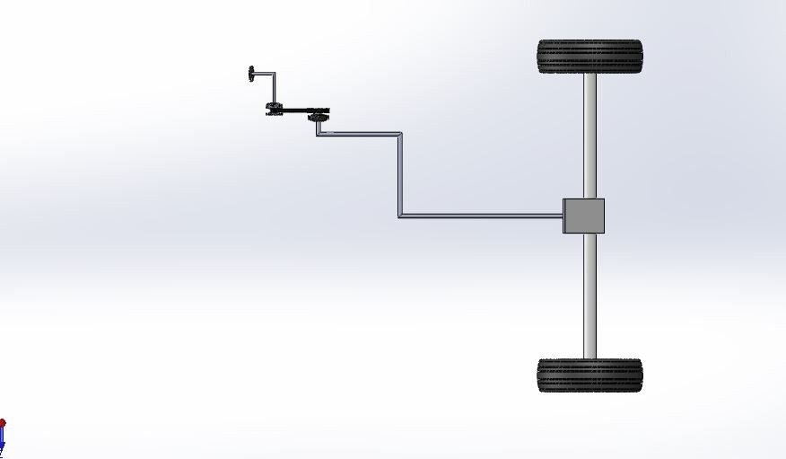
- Continuously variable transmission (CVT) – lets the flywheel speed change smoothly relative to the wheels
- Chain drive, brake drum, wheels and axle


Materials
| Material | Yield strength |
|---|---|
| Steel (existing) | 250 MPa |
| Stainless steel 304 | 300 MPa |
| Aluminium alloy 2048 | 415 MPa |
Static Structural Analysis of the Flywheel
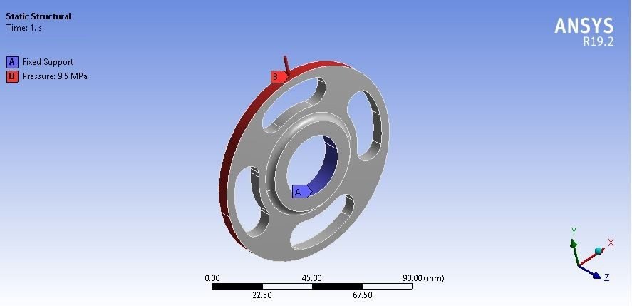
The flywheel was meshed in ANSYS Workbench. Its hub was fixed and a pressure of 9.5 MPa was applied to represent the load during energy storage.

| Result | Steel | SS 304 | Al-2048 |
|---|---|---|---|
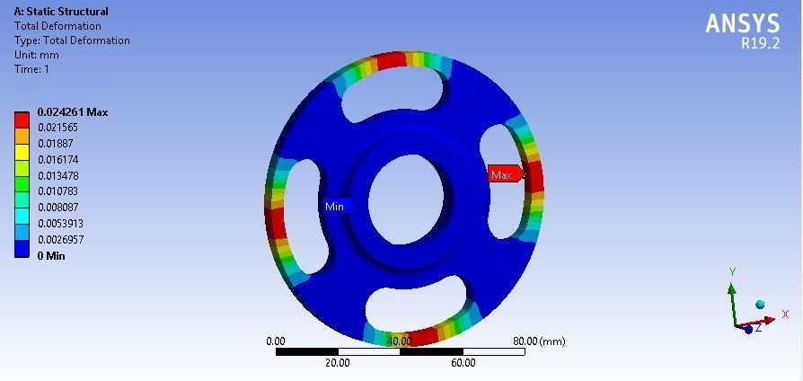
| Deformation (mm) | 0.024261 | 0.025413 | 0.069252 |
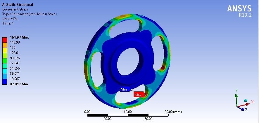
| Stress (MPa) | 161.97 | 161.93 | 162.09 |
| Strain | 0.00080983 | 0.0008478 | 0.0023156 |
| Safety factor | 1.5435 | 1.8527 | 2.5603 |

Modal Analysis
A flywheel spins fast, so its natural frequencies must stay well away from the running speed.
| Mode | Steel (Hz) | SS 304 (Hz) | Al-2048 (Hz) |
|---|---|---|---|
| 1 | 4594.5 | 4527.7 | 4610.5 |
| 2 | 4600.5 | 4534 | 4616.4 |
| 3 | 4609.5 | 4540.7 | 4632.1 |
| 4 | 5075.2 | 5021.3 | 5038 |
| 5 | 5273.4 | 5198.1 | 5290.4 |
| 6 | 7437.1 | 7351 | 7401.8 |

The stress stays nearly the same for all three materials, so the safety factor follows the yield strength, while the aluminium flywheel deflects more but weighs far less. The material recommended for the flywheel is explained in the project report.
Why Flywheel Design Matters
The energy stored in a flywheel rises with the square of its speed, so even a modest flywheel can hold a useful amount of energy if it spins fast. High speed, however, produces large centrifugal stresses in the rim and web. If the material is too weak, the flywheel can burst; if it is too heavy, it adds unwanted weight to the vehicle. Static and modal analysis together show whether the chosen material can hold the load safely and stay clear of resonance at running speed.
Real-World Applications
- Kinetic energy recovery systems (KERS) in race cars
- Buses, trains and delivery vehicles with frequent stops
- Hybrid mechanical energy storage
- Flywheel design for energy storage systems
Related Projects
Explore more design and analysis projects on similar topics:
- Electromagnetic Braking System: Design, Calculations and Component Analysis
- Two-Wheeler Disc Brake Rotor: Structural, Thermal and Modal Analysis
- Aircraft Disc Brake Rotor Design and Analysis: Al Metal Matrix Composite vs Al-7075 and CFRP (Structural, Thermal and Modal, ANSYS)
- Power Generation Using Shock Absorber: Rack and Pinion Energy Harvesting Design and Analysis (SolidWorks and ANSYS)
What You Get
- Design files: Calculations and SolidWorks models of flywheel, CVT, chain drive and wheels
- Analysis files: ANSYS static (9.5 MPa) and modal analysis of the flywheel
- Project document: complete report with methodology, results and conclusion
- Class explanation: a session that explains what was done in the project, step by step, so you can understand and present it confidently
Who Is This Project For?
This project suits B.Tech and B.E. final year students, diploma students looking for a strong design and analysis project, and M.Tech students who need a base model they can extend for their thesis. It is also useful for anyone who wants to learn How braking energy is stored in a flywheel and how material affects its strength on a real engineering problem instead of a textbook example.
Frequently Asked Questions
How does a flywheel regenerative braking system work?
During braking, the vehicle’s kinetic energy spins up a flywheel through a CVT, and the stored energy is released when the vehicle accelerates.
How much energy is stored?
The design calculation gives a braking kinetic energy of 7716.0493 J for the flywheel to store.
Which materials are compared?
Steel, stainless steel 304 and aluminium alloy 2048.
Which flywheel material is best?
The recommended material is explained in the project report.
Get the Regenerative Braking Flywheel Project
Want this project for your final year, mini project or M.Tech work? Message us with your university, branch and deadline, and we will share the exact scope, files and report format.
Enquire about this project on WhatsApp or use the enquiry form on our home page. Browse more mechanical projects or 60+ mechanical engineering project ideas.
Interested in this project? Get the details, files and guidance from our team.
Enquire on WhatsApp