
A clutch connects and disconnects the engine from the gearbox, letting the driver start smoothly, change gears and stop without stalling. In a single plate clutch, the most common type in cars, a friction plate splined to the gearbox input shaft is clamped between the engine flywheel and a pressure plate by springs. When the driver presses the pedal, the clamping force is released and power transmission stops. The clutch plate must carry the full engine torque through friction while resisting heat and wear. This project designs a single plate clutch and compares four materials.

Clutch Design Theory
Clutch torque capacity is calculated using two classical assumptions: uniform pressure, which applies to new clutches, and uniform wear, which applies after the friction lining has bedded in. The report works through both, calculating the mean friction radius, the axial clamping force, and the maximum, minimum and average pressure on the friction surface. The clutch plate modelled here has an outer diameter of 230 mm and a thickness of 5 mm.
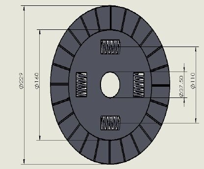
About the Project
The clutch plate is modelled in Creo and imported into ANSYS Workbench in IGES format. A pressure of 0.3 MPa is applied on the friction surface along with a torque (moment) load, and the plate is fixed at its hub. Two analyses are carried out:
- Static structural: deformation, equivalent stress, strain, shear stress and safety factor.
- Modal: the first six natural frequencies.
Four materials are compared: steel (existing), SS-304, SAE 1137 and Al-2048.

Software Used
- Creo: clutch plate modelling
- ANSYS Workbench: static structural and modal analysis
Analysis Results
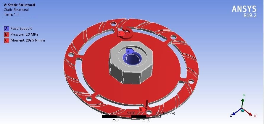


Key Results (Preview)
| Material | Deformation (mm) | Stress (MPa) | Shear stress (MPa) | Safety factor | Mode 1 (Hz) |
|---|---|---|---|---|---|
| Steel | 0.57083 | 153.58 | 81.451 | 1.6278 | 559.8 |
| SS-304 | 0.603 | 153.21 | 81.178 | 1.9744 | 555.46 |
| SAE 1137 | 0.58337 | 153.3 | 81.246 | 3.1833 | 557.22 |
| Al-2048 | 1.6187 | 154.55 | 82.183 | 2.6827 | 559.97 |
All four materials carry nearly the same stress, so the safety factor depends mainly on each material’s strength. Weight, cost and the final material choice are discussed in the project report.
Real-World Applications
- Cars and light commercial vehicles: manual transmissions.
- Tractors and trucks: heavy-duty single and twin plate clutches.
- Industrial machines: engaging and disengaging drives.
Key Concepts Covered
- Uniform pressure and uniform wear theories for clutch torque.
- Shear stress in torque-carrying plates.
- Modal analysis to avoid resonance at engine speeds.
Project Workflow
- Calculate clutch dimensions, clamping force and pressures.
- Model the clutch plate in Creo and export it as IGES.
- Apply 0.3 MPa pressure and torque in ANSYS.
- Run static and modal analysis for all four materials.
- Compare the results in the report.
Why This Project Matters
The clutch is one of the most important power transmission parts in any vehicle. This project combines design theory with FEA and is a great final-year choice for mechanical and automobile engineering students.
Related Projects
Explore more design and analysis projects on similar topics:
- Modelling and Analysis of a Multi-Plate Clutch with Kevlar and Carbon-Carbon Friction Materials (SolidWorks and ANSYS)
- Regenerative Braking System with Flywheel – Design, Static and Modal Analysis
- Electromagnetic Braking System: Design, Calculations and Component Analysis
- Tractor Rear Axle Shaft Design and Analysis: Mild Steel, Ni-Chrome and Invar
What You Get
- Design files: Creo model of the single plate clutch (with IGES file), with design calculations
- Analysis files: ANSYS Workbench static structural and modal analysis files for all four materials
- Project document: complete report with methodology, results and conclusion
- Class explanation: a session that explains what was done in the project, step by step, so you can understand and present it confidently
Who Is This Project For?
This project suits B.Tech and B.E. final year students, diploma students looking for a strong design and analysis project, and M.Tech students who need a base model they can extend for their thesis. It is also useful for anyone who wants to learn clutch design theory (uniform pressure and uniform wear), static and modal analysis in ANSYS on a real engineering problem instead of a textbook example.
Frequently Asked Questions
How does a single plate clutch work?
A friction plate is clamped between the flywheel and a pressure plate by springs. Pressing the pedal releases the clamping force and stops power transmission.
What is the difference between uniform pressure and uniform wear theory?
Uniform pressure theory applies to new clutches, while uniform wear theory applies after the friction lining has worn in. Uniform wear gives a slightly lower, safer torque capacity.
Which materials are compared?
Steel (existing), SS-304, SAE 1137 and Al-2048.
What loads are applied?
A pressure of 0.3 MPa on the friction surface along with a torque load, with the plate fixed at its hub.
Get the Single Plate Clutch Project
Want this project for your final year, mini project or M.Tech work? Message us with your university, branch and deadline, and we will share the exact scope, files and report format.
Enquire about this project on WhatsApp or use the enquiry form on our home page. Browse more mechanical projects or 60+ mechanical engineering project ideas.
Interested in this project? Get the details, files and guidance from our team.
Enquire on WhatsApp