
Vehicle exhaust contains harmful gases such as carbon monoxide, unburnt hydrocarbons like methane, and nitrogen oxides. A catalytic converter sits in the exhaust line and turns these into less harmful gases such as carbon dioxide, water vapour and nitrogen. Inside it, a honeycomb substrate with thousands of thin channels is coated with precious metal catalysts. The honeycomb gives a huge surface area in a small volume, so the hot exhaust touches as much catalyst as possible while flowing through with low back pressure. How evenly the gas flows through the honeycomb decides how well the converter cleans the exhaust.

Converter Design
The converter has an inlet cone that spreads the exhaust gas, a central shell that holds the honeycomb substrate, and an outlet cone that collects the cleaned gas. A second design with a modified air and fuel inlet arrangement is also modelled. The catalyst is taken as an alloy of platinum (40%), palladium (50%) and rhodium (10%), with an estimated density of about 6,000 kg/m³.

About the Project
The converter is modelled in SolidWorks and analysed in ANSYS Fluent with species transport, so the CFD tracks how individual gases such as CH₄, CO₂ and N₂ are distributed through the converter. The exhaust enters at a mass flow rate of 0.005 kg/s and a temperature of 600 K. Both a full 3D model and a simplified 2D model are studied.

Software Used
- SolidWorks: converter shell, cones and honeycomb modelling
- ANSYS Fluent: species transport CFD
Analysis Setup

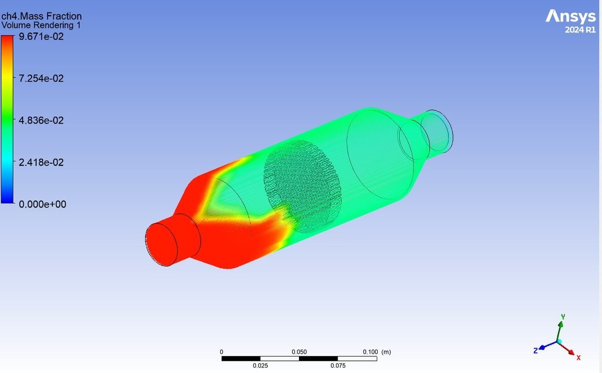
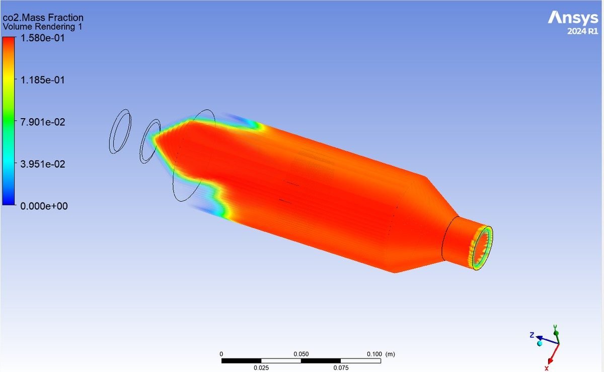
The species distribution results, the comparison of the two designs and the final conclusions are explained in the project report.
Why Flow Distribution Matters in a Catalytic Converter
A catalytic converter only works well if the exhaust gas spreads evenly across the whole face of the honeycomb. If the flow rushes through the centre and avoids the edges, the catalyst in the middle ages quickly while the outer channels hardly do any work, and harmful gases can slip through untreated. The shape of the inlet cone, the position of the inlet pipe and the length of the substrate all influence this distribution. CFD lets engineers see where the gas goes and how the species change inside the converter before any prototype is built, which saves time and expensive precious metal.
Real-World Applications
- Cars and two-wheelers: three-way catalytic converters for BS-VI and Euro 6 norms.
- CNG and LNG vehicles: methane slip control.
- Diesel generators: exhaust after-treatment.
- Industrial burners: emission control.
Key Concepts Covered
- Three-way catalysis: oxidation of CO and HC, reduction of NOx.
- Honeycomb substrates: surface area and back pressure.
- Species transport CFD: mass fractions of exhaust gases.
- Precious metal catalysts: Pt, Pd and Rh.
Project Workflow
- Study exhaust emissions and catalytic converter working.
- Model the converter and honeycomb in SolidWorks.
- Set up species transport in ANSYS Fluent.
- Run 3D and 2D CFD with 0.005 kg/s at 600 K.
- Compare species distribution in the report.
Why This Project Matters
Tighter emission norms make catalytic converter design a key automotive skill. This project gives hands-on experience with reacting-flow style CFD, a valuable topic for mechanical and automobile students.
Related Projects
Explore more design and analysis projects on similar topics:
- Exhaust Manifold Design Optimisation and Analysis: Two Designs, Four Materials (Static, Thermal and CFD in ANSYS)
- CFD Analysis of a Diesel Engine Combustion Chamber with Diesel and Rice Husk Biofuel Blends (SolidWorks and ANSYS Fluent)
- Design and Analysis of an Engine Mount Bracket: AISI 4140, Al 7075 and Ti-6Al-4V (SolidWorks and ANSYS)
- CFD Analysis of Parallel and Counter Flow Double Pipe Heat Exchanger with Al2O3 Nanofluids (SolidWorks and ANSYS Fluent)
What You Get
- Design files: SolidWorks models of the converter shell, inlet and outlet cones and honeycomb substrate, including a second design
- Analysis files: ANSYS Fluent species transport CFD files for 3D and 2D converter models
- Project document: complete report with methodology, results and conclusion
- Class explanation: a session that explains what was done in the project, step by step, so you can understand and present it confidently
Who Is This Project For?
This project suits B.Tech and B.E. final year students, diploma students looking for a strong design and analysis project, and M.Tech students who need a base model they can extend for their thesis. It is also useful for anyone who wants to learn SolidWorks modelling and ANSYS Fluent species transport CFD on a real engineering problem instead of a textbook example.
Frequently Asked Questions
What does a catalytic converter do?
It converts harmful exhaust gases such as CO, hydrocarbons and NOx into less harmful gases like CO₂, water vapour and nitrogen.
Why is a honeycomb substrate used?
It provides a very large catalyst surface area in a small volume while keeping back pressure low.
What boundary conditions are used in the CFD?
An exhaust mass flow rate of 0.005 kg/s at an inlet temperature of 600 K.
Which catalyst metals are considered?
An alloy of platinum (40%), palladium (50%) and rhodium (10%).
Get the Catalytic Converter CFD Project
Want this project for your final year, mini project or M.Tech work? Message us with your university, branch and deadline, and we will share the exact scope, files and report format.
Enquire about this project on WhatsApp or use the enquiry form on our home page. Browse more mechanical projects or 60+ mechanical engineering project ideas.
Interested in this project? Get the details, files and guidance from our team.
Enquire on WhatsApp